Welcome to Bond Graph Variables
As shown in Bond Graph there are two forms of the component
ports (see Figure 1):
• external ports or simply ports,and
• internal ports or
document ports.
To every external power port a pair of effort e and flow f varables are attached. What is the mathematical meaning of these variables? That depends on the structure of internal connections at the corresponding internal ports. Thus, as shown in the right part of Figure 1., the external effort e corresponds to the list of internal efforts e1, e2, e3, counting them from top to bottom, or from left to right, along the port (Figure 2.). Similarly, holds for the flow f.
Similar relationships hold for external control ports. There is an associated control c, which represents a list of control signals c1, c2, c3, ..., connected internally and counted the same way as the efforts and flows. The control port of Figure 1. is internally connected by only one control signal line.
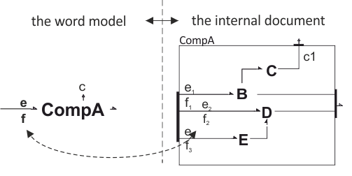
Figure 1. Effort and Flow Variables
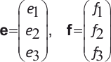
Figure 2. Effort and Flow Lists
We define dimension of a component port by the number of bonds internally connected to the corresponding internal (document) port, or number of variables in the list. Thus, the left power port in Figure 1. has dimensions of three because three bonds are internally connected to the port. These bonds are connected on the other side to internal components B, D, and E. These internal bonds are associated with the corresponding effort-flow variables. Thus, the entries to the internal ports are the lists as well. In this way the structure of external port variables are represented by a list of lists, i.e. a tree branch.