Welcome to Model of the Connecting Rod
The Figure down below shows Bond Graph model of the connecting rod. It consists of four Bond Graph
elements :
• 1-branch,
• two
transformers TF, and
• two 0-branches.
Note that the bottom document port has three connected bonds:
• the left one connected to the left port of the upper-left 0-branch,
• the middle bond connected
to the left port of the upper-right 0-branch,and
• the right bond connected to the bottom 1-branch port.
This is in agreement with discussion at the bottom of
support. Thus, the left bond transmit pair (FOx, vOx) effort flow variables, the middle one
(FOy, vOy), and the last bond transmits the variables (T,ω). Since the upper
0-branches are the nodes of the force components acting at the end point P, the forces at points O and P are equal:
FOx = FPx, and
FOy = FPx.
This is the consequence of the fact
that the rod has no mass.
The flows of the bottom ports of the transforms TF are equal to the transferred angular velocity to 1-branch. Due to transforms by TFs the flows at the above TF ports are components of the relative velocity of point P with respect to point O (see also relationships). The transform ratios are the coordinates of the point P. Finally, summing up the flows at the upper 0-branches gives the velocity components of the end rod point P.
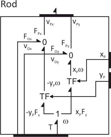
As shown in transform's constitutive relations, the Bond Graph TF transform the flows and efforts so that the power transfer do not change. As shown in the Figure up above this gives torque T equal to the sum of moments of forces at the upper TF's ports with respect to point O. This is again the the consequence of neglecting the rod's mass (i.e. the rod's the moment of inertia).
Next Back